
When a dump truck has a hydraulic problem, following the circuit one connection at a time can be more useful than replacing parts based on a guess. A dump truck hydraulic system diagram can look like a tangle of unfamiliar symbols, and its layout may differ from the truck in front of you. Misreading a line or assuming one symptom points to a single cause can send troubleshooting in the wrong direction. With a raised dump body, an unsafe inspection can also put you in serious danger.
This guide explains how to read the diagram as a flow path, identify its main components, and compare the drawing with the truck’s actual setup. You’ll see how fluid moves through the system, what common symbols and lines represent, and why a symptom is a starting point rather than a diagnosis. We’ll also cover when to stop and leave testing or repair to a qualified professional. Tim Halpin Equipment Corp provides dump truck and hydraulic repair for fleets in Miami and across South Florida, including Doral, Fort Lauderdale, Key West, Medley, Hialeah, and Kendall.
Key Takeaways
- Read the dump truck hydraulic system diagram as a connected fluid path, tracing how the reservoir, pump, control valve, and cylinder work together.
- Use the truck’s equipment-specific schematic where possible, since the pump drive, valve arrangement, hoist type, and installation can change the circuit layout.
- Compare the drawing with the actual truck before using it to interpret symptoms. A diagram can help narrow down the area to inspect, but it can’t confirm a fault on its own.
- Treat diagram-led troubleshooting as observation, not permission to work beneath an unsupported raised body or perform repairs beyond your training.
- Keep clear notes about the symptom and circuit area involved so a qualified hydraulic repair technician can continue diagnosis with useful context.
What a Dump Truck Hydraulic System Diagram Shows
A dump truck hydraulic system diagram maps the components and connections that move fluid through the truck. It shows how power reaches the hoist so the dump body can rise and lower. More than a parts list, the diagram illustrates how the circuit is intended to operate. Follow the lines and symbols to see how the components connect.
Pressure is the force applied to hydraulic fluid; flow is the fluid moving through the circuit. The pump supplies flow, while resistance from a load or a restricted path helps create pressure. When reading a schematic, remember that a line shows a fluid route, not the pressure at every point along it.
Dump trucks use different dump truck hydraulic lifting mechanisms, so treat a general illustration as a guide, not a blueprint for every vehicle. The truck, hoist design, and installed equipment determine the circuit layout.
Main components shown on a dump truck hydraulic schematic
Start by locating the reservoir, pump, control valve, and hydraulic cylinder. The reservoir stores fluid. The pump moves it through the system, and the control valve directs it according to the operator’s selection. The cylinder converts hydraulic energy into movement that raises or lowers the body.
Hoses and rigid lines connect the components, but they don’t all do the same job. A pressure line carries fluid from the pump toward the valve; a return line routes fluid back to the reservoir. Some circuits also include connections such as a power-beyond passage or a drain line. Follow the diagram’s labels and port markings rather than assuming that every line is interchangeable.
A power take-off, or PTO, may drive the pump by transferring power from the truck’s transmission. Other arrangements use a different pump drive. If the diagram shows a PTO, trace it as the pump’s power source, not as a hydraulic line.
How the diagram represents the raise-and-lower circuit
Start at the power source and trace the hydraulic route through the pump, valve, and cylinder. Then follow the return path. This sequence provides a useful framework for reading a detailed schematic:
- Power source: The engine and, where fitted, PTO turn the pump.
- Fluid supply: The pump draws fluid from the reservoir and sends flow toward the control valve.
- Valve selection: The valve directs flow to raise the body, holds the circuit, or allows the cylinder to retract for lowering.
- Actuator and return: The cylinder moves the hoist, while fluid follows the circuit’s return route according to the valve and system design.
In the raise position, the valve routes flow to the cylinder so it extends and lifts the body. In the hold position, the valve arrangement controls movement. For lowering, the valve provides a path for the cylinder to retract. The exact route and the role of gravity depend on the system design. Use this sequence to orient yourself, then match each symbol and connection to the truck-specific drawing.
How to Trace Hydraulic Flow Through a Dump Truck Diagram
Use the schematic as a route map, not as a picture of where parts sit on the truck. On a dump truck hydraulic system diagram, begin at the reservoir and follow each connected line to its next component. Pay attention to arrows, port labels, and valve positions. A line’s direction and destination matter more than where it appears on the page.
Follow the circuit from reservoir to hydraulic cylinder
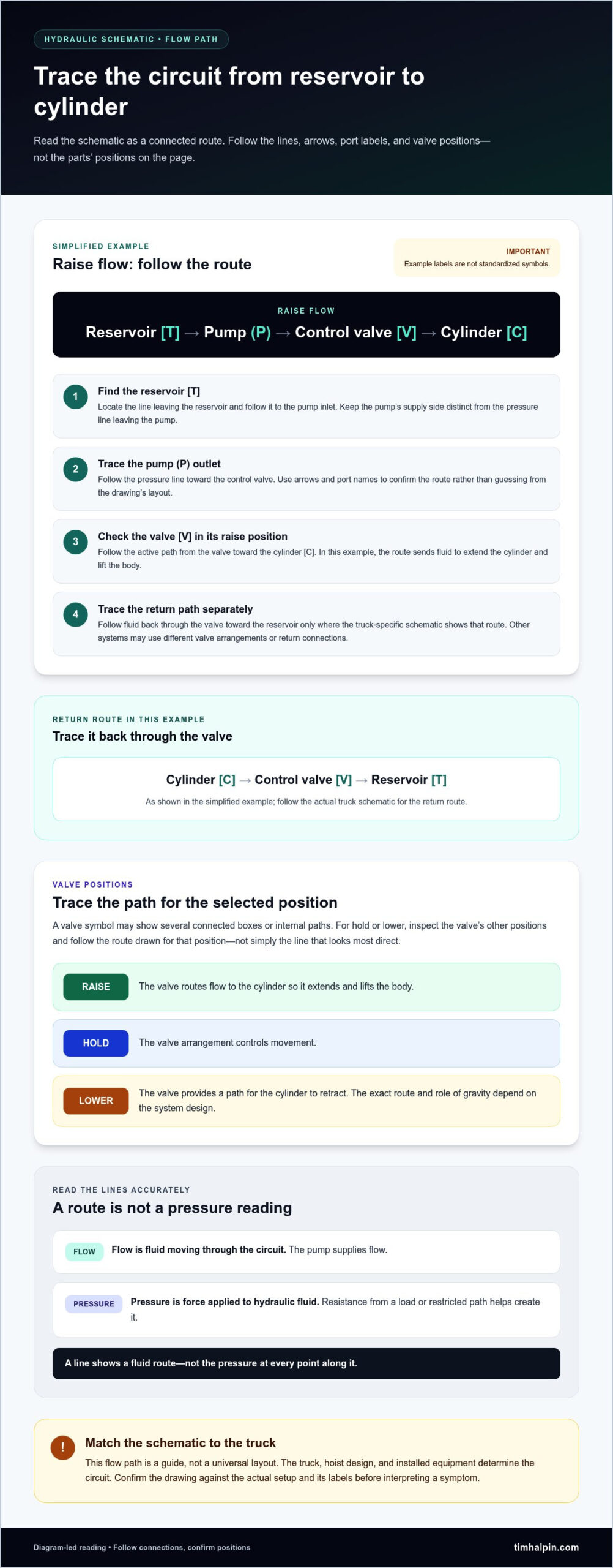
Trace the raise circuit in order. The example below shows a simplified flow path, not a universal layout. Its letter labels identify parts in this example and are not standardized component symbols.
Raise flow: Reservoir [T] → Pump (P) → Control valve [V] → Cylinder [C]
Return flow: Cylinder [C] → Control valve [V] → Reservoir [T], as shown in this simplified example
- Find the reservoir [T]. Locate the line leaving it and follow that line to the pump inlet. Don’t confuse the pump’s supply side with the pressure line leaving the pump.
- Trace the pump (P) outlet. Follow the pressure line to the control valve. If the drawing includes arrows or port names, use them to confirm the route instead of guessing from the component’s position.
- Check the valve [V] in its raise position. Follow the active path from the valve toward the cylinder [C]. In this example, that route directs fluid to extend the cylinder and lift the body.
- Follow the return path separately. Trace fluid back through the valve and toward the reservoir only where the truck-specific schematic shows that route. Other systems may use different valve arrangements or return connections.
For a hold or lower position, inspect the valve’s other positions and trace the paths shown there. A valve symbol can contain several connected boxes or internal paths. Follow the route for the selected position, not simply the line that looks most direct.
Read common hydraulic symbols without guessing
Hydraulic symbols describe a component’s function or connection, not necessarily its shape or mounting location. In the example, the labels mean:
- [T]: Reservoir, the fluid storage point in this example.
- (P): Pump, which supplies flow to the circuit.
- [V]: Control valve, which directs flow according to its position.
- [C]: Cylinder, the actuator shown receiving flow to raise the body.
- Arrow: The direction of flow for the illustrated operating state.
These are teaching labels, not a replacement for formal schematic notation. Real diagrams use standardized graphical symbols and may show ports, internal valve paths, and additional lines. Check the drawing’s legend and equipment documentation whenever a symbol or connection is unfamiliar. Tim Halpin Equipment Corp provides hydraulic repair for commercial trucks when diagnosis or repair requires hands-on support.
Why Dump Truck Hydraulic Diagrams Differ, and How to Match Yours
A schematic is useful only when it represents the system installed on your truck. A dump truck hydraulic system diagram may differ because of the pump drive, control-valve arrangement, hoist design, or equipment added during installation. Two trucks that look alike from the outside may route hydraulic lines differently beneath the body.
A drawing that resembles your setup isn’t proof that it matches. Treat it as a reference until component labels, ports, and connections line up with the actual equipment and its documentation.
Generic illustration vs. equipment-specific schematic
Generic circuit illustration: Shows a simplified arrangement of common components and their general relationships. It’s useful for learning the basic circuit, but it may omit truck-specific details or show a different configuration.
Equipment-specific schematic: Documents the intended connections for a particular truck, hoist, or hydraulic installation. Component identifiers, port labels, and routing details help you compare the drawing with the installed equipment.
Identify the installed hydraulic configuration
Start with what you can safely see. Without dismantling equipment, record the labels or model information on the pump, control valve, and cylinder, along with any identifying details on the hoist. Compare their arrangement and labeled connections with the schematic and manufacturer documentation. Check that the drawing corresponds to the truck or equipment configuration, not just a similar-looking model.
If a connection or component doesn’t clearly match, note the uncertainty rather than assigning it a purpose. A qualified technician can use those observations to identify the correct circuit and investigate further.
Avoid common diagram-reading assumptions
Use the drawing to guide your comparison, not to fill in missing information. These checks can help prevent a plausible-looking schematic from leading you in the wrong direction:
- Don’t assume every dump body uses the same pump drive, valve layout, or hoist arrangement.
- Don’t treat a line’s location on the page as proof of where a hose runs on the truck. Follow labels and connections.
- Don’t identify a failed component from one symptom or symbol alone. Different circuit issues can produce similar behavior.
- Keep model-specific manufacturer documentation with the truck’s maintenance records so it’s available for future reference.
When records include more than one schematic, label each drawing with the truck or configuration it applies to. If the installed parts don’t match the documentation, or a connection remains unclear, pause rather than guessing. Mark the uncertain point and share it with a qualified hydraulic technician. Accurate observations are more useful than an unsupported diagnosis.
Use the Diagram to Narrow Symptoms, Without Taking Unsafe Risks
A dump truck hydraulic system diagram can help you describe where a symptom appears in the circuit, but it can’t confirm the cause. Use it to organize observations and communicate them clearly, not as a substitute for repair training. A slow-moving dump body, for example, may involve more than one circuit, load, or operating factor. The same symptom can point to different issues on different trucks.
Safe observation means recording what you notice from a safe position; pressurized-system repair requires proper training and procedures. Never work beneath a raised dump body unless it’s properly supported and secured. Hydraulic pressure and an unsupported body can create serious hazards, even when the truck appears stationary.
Relate common symptoms to circuit sections
Note what the truck does, under what conditions, and whether the behavior changes. Then use the schematic to identify the circuit area involved without treating that area as a confirmed diagnosis.
- Slow lifting: Record whether the body moves slowly throughout the lift or only under particular conditions. Several circuit, load, or operating factors may contribute, so don’t assume the pump or cylinder is at fault.
- Drifting or uneven movement: Note when the body moves unevenly or doesn’t hold as expected. Record the circumstances and relevant circuit section rather than naming a failed valve or cylinder.
- Leaks or unusual noise: Stop operation and prioritize inspection. Don’t run the system to reproduce the symptom or move closer to a suspected leak.
- Loss of control: Stop using the system if movement is unpredictable. Keep people clear and arrange qualified diagnosis before returning the equipment to operation.
Useful notes include the body’s behavior, the operating condition when it happened, visible warning signs observed from a safe distance, and the circuit area indicated by the drawing. This gives a technician a clearer starting point than a guess about which part has failed.
Know when to stop and arrange hydraulic repair
Don’t loosen hydraulic lines or fittings to test for flow, and don’t touch or approach a suspected high-pressure leak. A fine jet of pressurized fluid can cause severe injury. If the body is raised, follow the manufacturer’s procedure to lower and secure it before inspection. Never rely on hydraulic pressure, a control valve, or an improvised support to keep the body raised while someone works beneath it.
Stop troubleshooting if the truck behaves unpredictably, the body can’t be secured safely, or the diagram doesn’t clarify the issue. A trained technician can compare the schematic with the installed circuit and perform the necessary hands-on diagnosis. For dump truck symptoms that remain unclear, arrange hydraulic repair with Tim Halpin Equipment Corp in Miami, serving fleets across South Florida.
From Hydraulic Diagram to Reliable Dump Truck Repair in South Florida
A correct schematic helps turn “the body is moving slowly” into a clearer account of what you observed and which part of the circuit may be involved. It gives you and a repair technician a shared reference, but it can’t reveal every fault on its own. Hands-on diagnosis may be needed to compare the drawing with the installed system and determine what’s causing the problem.
Use the dump truck hydraulic system diagram to support a clear handoff, not to settle on a diagnosis before the equipment has been inspected. Keep your notes factual: describe what happened, when it happened, and what you could safely observe. That context can make the next repair conversation more productive.
Prepare useful information before discussing a hydraulic issue
Gather details that help identify the truck and its hydraulic setup. There’s no need to remove components or get close to a raised body. Information from labels, records, and safe observations is a good starting point:
- Truck make, model, and identifying details available from records or labels.
- Visible pump, valve, cylinder, or hoist identification and model information.
- The symptom, when it occurs, and any change in lifting or lowering behavior.
- The relevant schematic or equipment documentation, if available.
Describe what you saw rather than guessing at the cause. For example, note whether movement changed under a particular operating condition, or whether you noticed a leak or unusual noise from a safe distance. Sharing the schematic can help repair staff understand which configuration you mean. If the diagram and visible components don’t seem to match, say so clearly.
Get hydraulic repair support in Miami and South Florida
Tim Halpin Equipment Corp is a family-owned Miami business providing commercial truck, dump truck, and hydraulic repair for South Florida fleets. The company connects diagram-led observations with practical repair support when a fault needs more than interpretation of the schematic. A technician can inspect the system directly to identify the cause and determine the appropriate repair.
When discussing hydraulic repair, share the truck details, symptoms, and available documentation. This helps keep the conversation focused on the equipment and the problem at hand. If you’re looking for truck hydraulics in Miami, contact Tim Halpin Equipment Corp about dump truck or hydraulic repair for your South Florida commercial vehicle.
Make Your Next Hydraulic Issue Easier to Address
Keep the correct schematic with the truck’s maintenance records, and update your notes when equipment changes. That habit gives your team a clearer starting point the next time a symptom appears. A dump truck hydraulic system diagram is most useful when it matches the installed setup and is paired with observations made safely.
If the cause remains unclear, don’t let a diagram become a reason to guess or keep operating an unsafe system. A clear description of the problem and the equipment involved can help move the conversation toward the right repair support. Tim Halpin Equipment Corp provides dump truck and hydraulic repair for South Florida commercial truck operators from its Miami base.
Contact Tim Halpin Equipment Corp about dump truck hydraulic repair to discuss your truck’s symptoms and repair needs.
Frequently Asked Questions
What does a dump truck hydraulic system diagram show?
It shows how hydraulic components and connections are arranged to operate the dump body. Depending on the schematic, you may also see port labels, valve positions, pressure-control components, or optional equipment. These details help explain how the circuit is intended to work, but the drawing doesn’t necessarily show where each part sits on the truck. Check its title and equipment references to understand which system it represents.
How do you read a dump truck hydraulic schematic?
Start by checking the drawing title, legend, and any notes that identify the circuit or operating state. Then follow one line at a time, using port labels and connection symbols to see where it leads. A line crossing another isn’t always a connection, so check the diagram’s junction convention before tracing across it. If an unfamiliar symbol affects your interpretation, consult the equipment documentation rather than guessing.
What are the main components in a dump truck hydraulic system?
Common components include a fluid reservoir, pump, control valve, hoses or rigid lines, and a hydraulic cylinder. A schematic may also show items such as filters, pressure-relief valves, or gauges when they’re part of that installation. These additional components can help explain how fluid is managed or how pressure is limited. Don’t assume every truck has the same components or that an omitted item is missing from the actual system.
Why does my dump truck hydraulic diagram look different from another truck’s?
Dump trucks can have different hoists, pump drives, valve arrangements, and equipment installations, so their schematics may show different connections. The drawings may also refer to different equipment versions or revisions. If a diagram looks familiar but the labels or ports don’t match, don’t rely on appearance alone to confirm it applies. Compare the document’s identifiers with the truck’s equipment records and visible labels before using it.
Can a hydraulic diagram tell me why my dump truck will not lift?
A diagram can help you identify which parts of the circuit are involved, but it can’t confirm why the body won’t lift. The issue could involve the power source, controls, fluid path, or another part of the installed system. Record whether the body moves at all and what was happening when the symptom occurred. Share those observations with a qualified technician instead of replacing a component based on the drawing alone.
Is it safe to inspect hydraulics with the dump body raised?
Never work beneath a raised dump body unless it’s properly supported and secured according to the manufacturer’s procedures. Hydraulic pressure alone isn’t a safe support, and a body can descend unexpectedly. Keep clear of suspected leaks and don’t loosen fittings or touch a high-pressure fluid jet. If you can’t lower or secure the body safely, stop and arrange qualified assistance before inspecting the system.
When should I call for professional dump truck hydraulic repair?
Arrange professional diagnosis if the truck has an active leak, unpredictable movement, unusual noise, repeated lifting trouble, or a body that can’t be lowered or secured safely. Tim Halpin Equipment Corp provides dump truck and hydraulic repair from Miami for customers across South Florida, including Doral, Fort Lauderdale, Medley, Hialeah, Kendall, and Key West. Share the symptom and available equipment documentation so the repair discussion can start with useful details.
